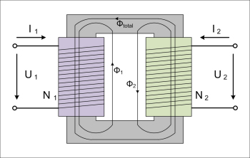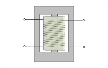
A transformer is a device that converts a voltage to a magnetic field and then back to a voltage again. It produces a related AC output signal without the input and output being physically connected together.
Transformers are AC only devices (operation depends on a changing magnetic field) and can be designed to operate at frequencies from about 0.01 Hz to many GHz. Generally those operating under about 1 MHz use multiple windings or turns of wire around the core of magnetic material to confine and concentrate the magnetic field. They are used to perform a variety of functions, like phase reversal,
balanced to unbalanced coupling, impedance transformation and hybrid functions.
An isolation transformer connected between two pieces of audio equipment will prevent the flow of circulating earth currents, because there is no electrical connection between the input and output of the transformer (the audio signal is coupled only magnetically).
The physical size of audio transformers is dependent upon the lowest frequency and the power available at that frequency.
Transformers can be manufactured with multiple primary or secondary windings.
The input winding is called the primary side and the output (or load) winding is called the secondary side of the transformer. The input and output windings are electrically insulated from each other.
To prevent external magnetic fields from generating unwanted signals into the transformer, a magnetic shield around the transformer itself is also required.

Transformers are generally used to change the voltage or to isolate the input and output voltages. The primary to secondary voltage ratio is directly proportional to the primary to secondary winding turns ratio.
The voltage ratio of a transformer is directly related to the winding turns ratio, the relationship of current is vice versa:

A step-up transformer is one whose secondary voltage is greater than its primary voltage. It steps up the voltage applied to it.
A step-down transformer is one whose secondary voltage is less than its primary voltage. It steps down the voltage applied to it.
As an example, a transformer with a ratio of 10:1 (primary/secondary) has a turns ratio of 10:1 and a voltage ratio of 10:1. It is a 'step-down' transformer and would transform a primary voltage of 10V into a secondary voltage of 1V.
The secondary voltage (VS) equals the ratio of secondary to primary turns multiplied with the primary voltage (Vp):
A transformer that steps up voltage will step down current and a transformer that steps down voltage will step up current because of the fact that the power dissipated in the primary of a transformer is (in theory) equal to the power dissipated in the secondary:
PS = PP
A 10:1 transformer for instance matches low-impedance sources to high-impedance inputs or high-impedance sources to low-impedance inputs.
An easy to misunderstand point is the impedance of a transformer:
Transformers can be used to step-up and step-down impedances with turns ratios, the same way that voltages can be stepped-up and down, but the relationship isn't as simple as with voltages.

The transformer itself has no inner impedance, it simply reflects the secondary load impedance (modified by the square of the turns ratio, to the primary).
For instance: An impedance of 2.5 kOhms should be connected to an impedance of 4 Ohms:
Turns Ratio = square root of (2500 / 4)
Turns Ratio = square root of 625 = 25
The turns ratio is 25:1. The primary side of the transformer needs to have 25 times as many turns of wire as the secondary. If the primary has 1,000 turns, the secondary would have 1,000/25 = 40 turns.
An 600 to 600 ohms impedance matching transformer can be used to match any impedance from 100 to 10k ohms with little degradation in frequency response.
Material: Low level audio transformers are normally wound on mu-metal cores, although some specialized types are wound on ferrite. High level audio transformers are more or less all wound on grain oriented silicon steel.

Distortion: The distortion of a transformer is due to the hysteresis of the magnetic material. It is caused by irregularities in the inner structure of the magnetic material. Distortion is not obviously a problem in power transformers, in audio line transformers it can make all the difference.
Low distortion and high performance transformers are made by using special core materials with a very uniform crystalline structure.
To guaranty good lo-frequency response requirements, the primary inductance of the transformer must be enormously high. It can require wire turns of many thousands with a very small wire diameter. Primary inductance of more than 1000 Henries are common. The downside is, that the small wire diameter and the large number of turns necessary for an excellent lo-frequency response reduces the high frequency response (higher capacitance). A perfect transformer is a compromise of both obtained by special layering and interleaving windings.
An often heard theory: "Basically a transformer slows down upper frequencies and allow the low frequencies to pass first, creating what we perceive as a "fat/warm" tone." ??
1:1 transformer: Called an isolation transformer, it has the same number of windings on the primary and the secondary side. The signal level does not change because of the same impedance for the primary and secondary.
Balanced center tapped transformer: A balanced line consists of three conductors with one at ground and two signals identical but 180 degrees out of phase with each other. Any external induced noises will be equally carried by both signal wires and canceled because they are 180 degrees out of phase.
Jensen Transformers